
-
Menu -
Locations -
Search
Features
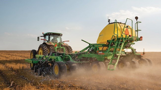
SurePoint Ag liquid tank options for select N500 Air Drills
 John Deere N543F 1892.7 L (500 gal.) hitch mounted tank kit
John Deere’s partnership with SurePoint Ag gives dealers confidence they have access to the best liquid fertilizer options for their customer’s needs. SurePoint’s very first application systems were configured for Air Seeders as a result of our roots in the High Plains winter wheat region. As with any fertilizer system, having the right tank configuration is a key part of ensuring that your application system performs the way it was designed. With the series of tanks for select N500 Series Air Drills, you are getting a well-integrated and well thought out tank design for liquid solutions in your operation.
The N500 Series of tanks deliver the things you need to complete an efficient system:
- Capacity – 1892.7 L (500 gal.) to meet most any need
- Balance – mounted to the hitch to spread the weight evenly across your air drill and provide for better flow
- Visibility – is it out of the way so it does not inhibit line of site,
- Quality – built tough to withstand the wear and use that can take place on your farm and in the field
- Accessibility – is easy to install and easy to access for filling or maintenance
- Support – service and parts availability when needed
- Integration – designed with SurePoint Liquid Application Systems in mind
The support frame is a modular design for easier shipping and installation. The frame cradles the poly tanks providing a secure and solid platform. This setup also provides for better fore and aft weight distribution across your tractor and air drill.
Hitch mounted tanks are available for the following models of Air Drills:
- N530C
- N536C
- N540C
- N542C
- N543F – will not work with seeder applying dry fertilizer
SurePoint Ag will work with you to select the right size and style of tank to keep you moving forward, in any applications, to achieve the as much productivity as possible! Talk with them today about all the custom application offerings they have available for your Air Seeder.
 Liquid tank installed on an N500C
The Total Seeding Solution – experience the John Deere advantage
John Deere has the seeding solutions that go above expectations with a complete line of everything needed in small grains. Offering a variety of openers for your chosen practice in a variety of configurations and sizes. All with integrated technology throughout the seeding train allows for effortless setup and seamless documentation.
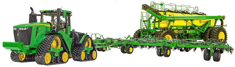 Total seeding solution
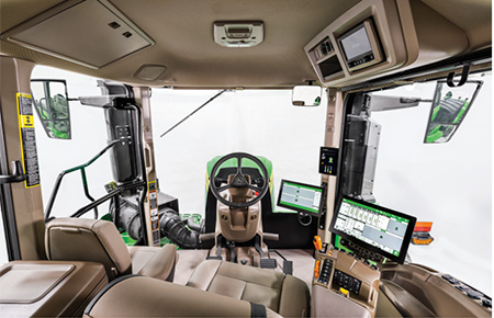
Setting up a John Deere seeding train is quick and easy with the plug and play technology. All data and technology operate through a Gen 4 or G5™ display and ultimately up to John Deere Operation Center™ that can be viewed from anywhere at any time. Not only does the complete John Deere seeding solution all operate through one display but it eliminates the difficulty and time-consuming tasks of setting up extra displays and harnesses.
 John Deere tractor paired with John Deere tool and cart
With a complete John Deere seeding solution, there are multiple different onboard and offboard technologies shown below that improve the overall seeding production step. Many of these technologies are exclusive to John Deere. Each of these technologies bring different customer value that overall lead to the ultimate John Deere seeding solution!
Improve confidence and while reducing maintenance with the AccuRate™ metering system
- Combination of stainless steel and composite materials ensure an entire corrosion resistant system
- Individual electric meters allowing for more precise seeding
- Up to 8x more accurate prescriptions with high fidelity prescription
- Start and stop each meter with SectionCommand™ Pro
- Accurately meter the correct amount of product on a curve with curve compensation
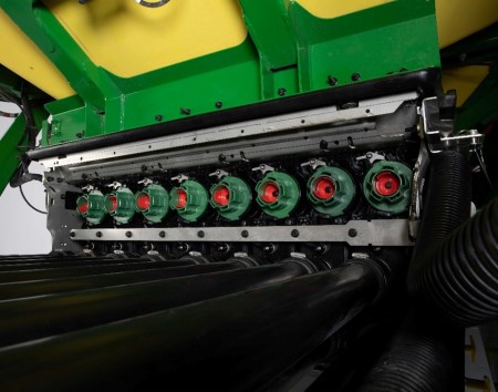 AccuRate™ meters showing eight individual sections
Calibrate faster and easier than ever before with EZCal™
- Easily calibrate from the side of the cart with the click of a few buttons 45% faster than the leading competitor
- Automatically weigh product and update MDV values eliminating potential user error
 G5e Cart Side Display
 EZCal™ system
Calibrate more frequently from the seat of the cab with ActiveCal™
- Calibrate the meters from the cab utilizing the tank scales
- Improved confidence that the correct seeding rates are being met
 ActiveCal™ display
Simplify bulk bag handling with EZLift
- Eliminates the need for additional tractors, picker trucks, or telehandlers in the field, reducing field logistics
- Direct bulk bag unloading into tanks 1, 2, and 3 speeds up the refill process and minimizes downtime
NOTE: EZLift is only available on the C1100T air cart
 EZLift and side storage platform
Save input cost with SectionCommand™Pro
- Control seed and fertilizer output by starting and stopping each individual meter section
- Eliminate skips and overlaps leading to reduced inputs and higher yields
 Example of seeded field with SectionCommand™ Pro
On the go, quick adjust downforce with TruSet™ from the cab
- Adjust downforce pressure to improve uniform emergence
- Set presets to quickly adjust from field to field
 TruSet downforce display
Monitor blockage row by row from the cab with RelativeFlow™
- Seed with confidence while monitoring each row
- Detect blockage early and know exactly where it is
 RelativeFlow blockage sensors
AutoTrac™ Implement Guidance and AutoTrac Turn Automation
- Make every operator an experienced operator
- Precisely placed implements for more accurate seeding, less operator fatigue, and more productivity
- Hands-free turns within field headlands (with AutoTrac Turn Automation enabled)
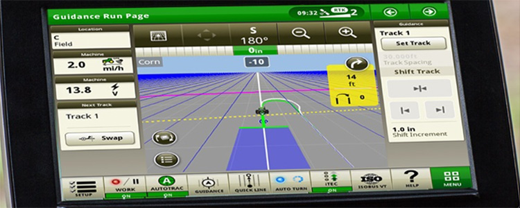 AutoTrac Turn Automation display
John Deere Operation Center™
- Setup and manage your farm operations: equipment, team, fields, and crop inputs
- Plan work in advance to increase job quality and efficiency with Work Planner
- Map based prescriptions can be used with variable rates
- Analyze this season’s results to improve next season’s crops
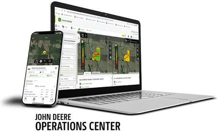 John Deere Operation Center web and mobile
Operation Center Mobile
- View your data on the go; remotely monitor job quality, productivity, machine performance, and quickly make informed decisions
- Manage and monitor from anywhere at any time with near real-time field and machine updates
 Operation Center Mobile
Connected Support
- Expert Alerts proactively notifies your dealer of any issues
- Remote display access allows for easy on the go support
 Connected Support
For more information regarding Large Tractors and Precision Ag, view the following landing pages
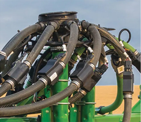
Color-coded hydraulic hose handles
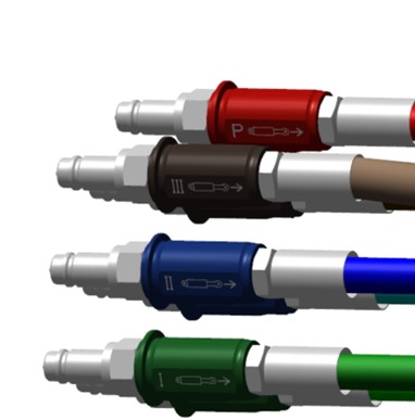 John Deere color-coded hydraulic hose handles
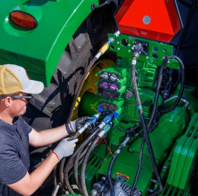 Color-coded hoses plugging into tractor SCV
These color-coded aluminum hydraulic hose handles make connecting hydraulic hoses from the air seeder and air cart to the correct Selective Control Valve (SCV) on the tractor easier than before. The anti-slip makes it easy to grip the hose and connect or disconnect from the back of the tractor. Each color is laser engraved with the John Deere logo and extend/retract icons to ensure proper matching to the proper function.
- Easily identify function of each hose
- Consistently match hose handles colors to rear couplers on tractor
- Easy to grip for connecting or disconnecting to the SCV
- Base equipment on all trailing air carts
- Base equipment on all seeding tools
Improved meter access with new frame design
The tank on the N500C has been moved up and back to allow for better access to the meters. The blower fan has been relocated to the front of the tank to allow non-obstructed access to all four meters.
 Rear of N500C machine
 Relocated blower fan
 Easy meter access
The updated tank design is also larger. The 9.15-m (30-ft) to 11-m (36-ft) models offer a 3523.9 -L (100-bu) tank. The 12.2-m (40-ft) and 12.8-m (42-ft) models offer a 4228.7-L (120-bu) tank.
 3523.9-L (100-bu) tank
Tank cleanout has also been improved. Producers can place a seed box or conveyer under the tanks to empty out excess seed. The tank has been designed so there is minimal seed left in the tank after it has been emptied.
 Cleanout with a seed box
 Cleanout with seed tender
Calibrating the meters has also been improved thanks to electric drive metering. The N500C is calibrated stationary similar to larger air carts. Catch bags are placed under each meter, and the meters turn a pre-determined amount of revolutions. Catch bags are weighted and entered into the Equipment Mobile app or on the Gen 4 display in order to generate a meter displacement value (MDV).
 Calibrating the meters
Electric drives enabling SectionCommand™ system
For the first time, meter sections are controlled with electric motors. Each meter section has its own electric drive motor. This eliminates the need for a variable-rate drive hydraulic motor or a ground drive wheel. This also enables the SectionCommand system and variable/prescription seeding.
 Electric drive motor on meter
 SeedStar run page showing four sections and prescription (Rx) seeding
Prescription/variable-rate seeding allows growers to apply the right amount of seed depending on predetermined management zones. Four-section SectionCommand has shown a potential seed savings of 4 to 6 percent depending on field size and shape.
Power generation
The electric motors are powered by a DC/DC convertor. The DC/DC convertor utilizes power coming from the tractor though the ISOBUS nine-pin connector and converts it to 56 V; this results in fewer moving parts and decreases the opportunity for downtime to occur.
 DC/DC power generation
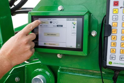
Calibrate from the cab with the John Deere ActiveCal™ system
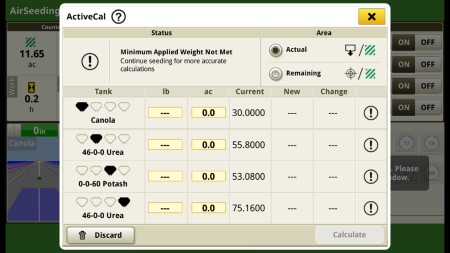
 ActiveCal tanks selected on C-Series Air Carts
 ActiveCal status page with MDV values
Overview
As circumstances evolve, it is essential to keep the meter displacement value (MDV) up to date. John Deere ActiveCal™, available on the N500C and all C-Series Air Carts, enables operators to maintain precise meter calibrations from the cab by using the individual tank scales on the air cart. This allows you to update your MDV as needed and as often as you prefer, all from the cab, without causing any downtime.
Using ActiveCal is straightforward. While stationary, activate the feature by selecting the button on the display screen and then start seeding. Once a sufficient amount of product has been metered, typically after about 8 to 12 acres (3.2 to 4.9 ha), the display will prompt the operator to stop at a convenient time. At this point, the data points are calculated, and a new MDV with the percentage difference is displayed on the screen. The operator can either accept or reject the new MDV. If accepted, the system automatically calibrates to the new MDV. If rejected, the system continues with the previously calibrated values.
Benefits
- Convenience: ActiveCal allows you to update your MDV value from the cab without having to stop the machine, reducing downtime.
- Accuracy: By maintaining precise meter calibrations, you can ensure that the seeding process is more accurate and efficient.
- Ease of use: ActiveCal is simple to engage and use, making it accessible for operators of all experience levels.
- Adaptability: The feature allows you to update your MDV as needed and as often as you prefer, ensuring that your machine is always calibrated for optimal performance.
- Automatic calibration: If the new MDV is accepted, the system automatically calibrates to the new value, streamlining the process and saving time.
 Tank scales provide tank weights to ActiveCal system
Equipment Mobile mobile app
 Equipment Mobile app home screen
Tank scale weights and meter calibrations can be completed from an Android™ or iOS® mobile device anywhere around the machine.
 Calibrating tank scales
 Calibration complete
Tank scale weights can be viewed anywhere within 15.2 m (50 ft). The Equipment Mobile app can also be used to calibrate the tank scales as needed.
Initial meter calibration
 Select meters to calibrate
Select the meters that toned to be calibrated. Calibrations are recommended every morning or when crops/seed sizes are changed.
 Steps to complete calibration
Follow the on-screen prompts to complete the calibration.
 Press meter calibration switch
Once the catch bags are in place, hold down the meter calibration switch until the number of revolutions is complete.
 Weights of bag for each meter
 Entering the weight of the bags
Enter the weights of the bags into the app.
 Save meter displacement values (MDV)
 MDV values are updated
The Equipment Mobile app will calculate MDV based on the number of revolutions and the product weights. Operators can choose to accept the proposed MDV values or not.
Android is a trademark of Google LLC. iOS is a trademark of Cisco Technology, Inc. used under license by Apple Inc.
Confidence in rates from row to row with RelativeFlow™ Blockage sensing
With RelativeFlow Blockage sensing, operators can see the flow of both seed and fertilizer from inside the tractor cab. Sensors on all secondary hoses monitor the relative product flow row to row, giving you a better view of the flow rate of both seed and fertilizer from the cart to the opener from inside your tractor cab. This technology can help you identify any problems before a potential blockage occurs.
RelativeFlow Blockage is available in all run configurations on the following models (all widths):
- H500
- H500F
- P500
- P600
- N500
- N500F
- N500C
- 730LL
RelativeFlow Blockage is compatible with hydraulic drive carts: model year 2014 and newer 1910, all 19,381.5-L (550-bu) 1910 Carts, and C650 and C850 Air Carts.
Below are the Gen 4 display screens for the blockage monitoring system. For complete details and information, see the owner’s manual.
 Blockage monitoring screen on Gen 4 display
The RelativeFlow Blockage sensing chart shows the amount of flow through each sensor on the selected tower. Sensitivity for the blockage system can be adjusted if desired, as shown below.
 Blockage Setup screen on Gen 4 display
Blockage warning sensitivity allows the producer to set and change the sensitivity of the sensors to meet their preferences and varying crop/fertilizer types. Increasing the sensitivity means the system is more likely to show a false blockage, while less sensitivity means the system is more likely to miss a blockage.
Multiple run-page alarm behavior options are available for selection.
 Blockage monitoring screen on Gen 4 display
Below are the Gen 4 display screens for the blockage monitoring system on the N500C.
For complete details and information reference, the owner’s manual.
 RelativeFlow Blockage configured run page
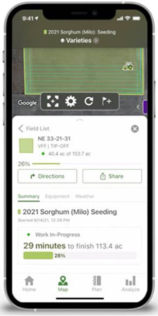
The SeedStar™ system run page displays the five major run settings. Clicking on any of the tiles will take an operator to that specific page (shown below).
 Operators can zoom into flow details by meter section when selecting blockage tiles
 Operators can zoom into the row level to access row/sensor information and turn a sensor on/off independently
 Blockage sensitivities and alarm delays are all set up on one easy-to-navigate screen
Blockage alarm delays can be set up by clicking on the advanced settings button from the blockage set-up screen.
- A blockage delay is how long a blockage should occur before an alarm is sounded.
- The blockage alarm reminder is how often the alarm should sound when a blockage occurs.
- The meter on delay is the time from when the meter is turned on until the blockage sensor should start monitoring for blockage.
- The meter off delay is the time from when the meter is turned off until the blockage sensor should start monitoring to verify no flow.
For more detailed information, see the owner’s manual.
Air tools with RelativeFlow Blockage are not compatible with 1910 air carts with ground drive.
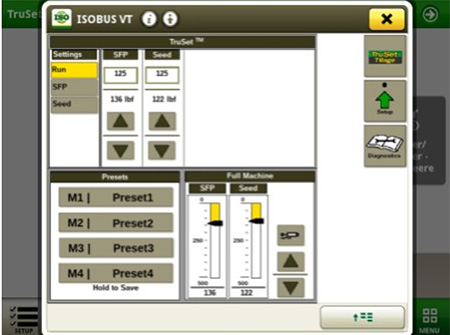
Improve seed placement accuracy from the cab with TruSet™ downforce control
 Downforce control from the Gen 4 display
TruSet downforce allows operators to set downforce pressures from inside the cab. Downforce can easily be changed by the push of a button as soil conditions very. Proper downforce is directly related to a consistent seeding depth, which leads to improved even emergence, plant density, and maturity.
TruSet system quick-reference guide

TruSet downforce settings:
A. Select to manually input a value
B. Select to increase or decrease the target force of the openers
C. Downforce toggle button: select to enable or disable the downforce
D. Indicates that the downforce is enabled
E. Indicates that the downforce is disabled
F. Indicates that the downforce is enabled but not applying
Get into the field sooner and stay longer with high floatation tires
The N500C offers 33x15.5R16.5 tires standard on all machines, resulting in better floatation and less compaction and allowing operators to get into the field sooner and stay in the field longer. The mainframe is also equipped with walking beams to allow for better ground following.
 500/40R16.5 tires with walking beam
 33x15.5R16.5 tires with walking beam
 31x13.5R15 tires on wing frame
| Option code | Width | Mainframe front tire size | Number of tires | Mainframe rear tire size | Number of tires | Wing frame tire size | Number of tires |
| 3610 | All | 33x15.5R16.5 | 4 | 33x15.5R16.5 | 4 | 31x13.5R15 | 4 |
| 3611 | All | 33x15.5R16.5 | 4 | 33x15.5R16.5 | 4 | 31x13.5R15 | 8 |
| 3612 | 9.5/11-m (30/36-ft) |
33x15.5R16.5 | 4 | 500/40R16.5 | 4 | 33x15.5R16.5 | 8 |
| 3613 | 12.2/12.8-m (40/42-ft) |
500/40R16.5 | 4 | 500/40R16.5 | 4 | 33x15.5R16.5 | 8 |
 Tire area comparison
Versatile machine configurations
 N500C with SeedMetering2
 N500C in the field
The N500C is designed for no-till seeding. The N500C with SeedMetering2 offers accurate volumetric metering in a compact tank-mounted-on-frame design, with the convenience of the Central Commodity System (CCS™) bulk-fill capabilities.
The N500C is available in single- or dual-rank designs, with 9.15-m, 11-m, 12.2-m, and 12.8-m (30-ft, 36-ft, 40-ft, and 42-ft) working widths. The single-rank N500C is available in 38.1-cm (15-in.) row spacing, making for a highly productive soybean seeding machine, while the dual-rank models are available in 19-cm or 25.4-cm (7.5-in. or 10-in.) row spacings. The dual-rank models also feature an optional dual row spacing package, which allows them to seed in their standard spacing or lock-up one rank and seed in 38.1-cm or 50.8-cm (15-in. or 20-in.) row spacings.
The productivity of the CCS comes standard with the N500C. The CCS bulk-fill tanks feature 3523.9-L (100-bu) capacity on the 9.15-m (30-ft) to 11-m (36-ft) models. The 12.2-m (40-ft) and 12.8-m (42-ft) models offer 4228.7 L (120 bu) of capacity to allow operators to seed more acres before stopping to refill.
The N500C features the Pro-Series™ No-Till Openers. With well over one million no-till openers in the field today, this proven opener offers accurate seed placement with the exclusive active hydraulic downforce ground-following system while minimizing moisture loss with its low-disturbance opener design.
No-till opener seeding with minimal maintenance from the ProSeries™ Opener
 ProSeries Openers
The ProSeries Opener is John Deere’s most advanced opener for your seed and separate fertilizer placement. When it comes to seeding precision, consistent seed depth, and uniform emergence in virtually all field conditions, you can superSEED your expectations with ProSeries.
Two of the three daily grease points were removed. The only remaining grease point is a yearly interval. The narrow seed boot travels behind the shadow of the blade, causing less soil disturbance. When attaching the boot to the shank, the bolt has been replaced with a flag pin. Now the flag pin is the wear point, not the casting, reducing overall maintenance. The seed press wheel is also redesigned; it has a narrow profile, a double row ball bearing, and is made of a flexible material. The quick-change blade feature reduces the time it takes to change each blade, saving time and money. Lastly, the seed tab is UV resistant and profiled similar to the trench. There is also the added option of the serrated closing wheel.

ProSeries Openers are in base equipment on all N500 and N500F Separate Fertilizer Placement (SFP), N500C, 1990 Central Commodity System (CCS™), and 1590 Air Drills.
The ProSeries Openers:
- Work not only in no-till conditions, but also in minimum or reduced-till conditions
- Provide 51 mm (2 in.) of free travel in the opener before spring down pressure takes over
- Benefit: allows the opener to move over uneven ground conditions and minimize the chance of the gauge wheels bulldozing soil in soft or mellow conditions
- The opener spring travels a maximum of 203-mm (8-in.) up or 150-mm (6-in.) down before the hydraulics react to uneven seedbeds
John Deere Seeding cover crop solutions
Why cover crops?
With proper management and the right selection of cover crops, you can slow soil erosion, improve soil health, enhance water availability, suppress weeds, control pests and diseases, increase biodiversity, and reap numerous other benefits for your farm’s health and profitability. Cover crops act as a protective shield for the soil, reducing the impact of heavy rains and wind, which in turn minimizes topsoil loss. They improve soil structure by adding organic matter and fostering beneficial soil microorganisms, which enhances nutrient cycling and retention.
Additionally, cover crops can break up compacted soil layers, improving root penetration and water infiltration. By suppressing weeds, they reduce the need for chemical herbicides, leading to more sustainable farming practices. Cover crops also provide beneficial habitat for insects and pollinators, boosting on-farm biodiversity. Furthermore, they can help in sequestering carbon, contributing to climate change mitigation. Overall, integrating cover crops into your farming system can lead to more resilient and productive agricultural landscapes, ultimately enhancing long-term profitability.
What tool works best for you?
 N500C No-Till Air Drill
The N500C model machines provide extensive crop compatibility, making them an excellent choice for customers looking to seed multiple crops and crop blends using a single tool. These machines can be customized with two unique rollers in multiple sizes to meet the specific needs of each operation. Refer to the crop compatibility link by roller below. Additionally, the N500C is capable of seeding in various soil conditions and residue types. Featuring the Pro-Series No-Till opener, it is designed to handle a wide range of conditions, from heavy residue to lightly worked soils. For more information, see the Sales Manual links below.
 1590 No-Till Box Drills
Box Drills are an excellent choice for seeding cover crops, offering simplicity and high placement accuracy. Equipped with the Pro-Series No-Till opener, the 1590 Box Drill can handle a variety of conditions, from heavy residue to lightly worked soils. The 455 and BD11 Series Box Drills, featuring a double disk opener, are ideal for tilled seed beds. They also provide wider widths and a range of spacing options. For more information, see the Sales Manual link below.
Already have an Air Seeder?
 C-Series Air Cart tendering
Any John Deere air cart compatible tools are excellent options for seeding cover crops. Air carts come with multiple tanks, enabling you to combine or blend your cover crop mixes effectively. With a wide range of meter roller options, air carts can be easily tailored to meet your specific cover crop needs and paired with the most suitable tool for the job. For more information, see the Sales Manual links below.
Specifications
Key Specs
| Working widths | 12.2 m 40 ft |
|---|---|
| Spacing | Dual rank: 7.5-in. (19.1 cm) spacing; 10-in. (25.4 cm) spacing Single rank: 15-in. (38.1 cm) spacing |
| Number of ranks | Single; Dual |
| Openers | Style No-till Rank lock-up Individual Diameter 45.7 cm 18 in. Down pressure 74.8-181.4 kg/opener (165-400 lb) Dual rank - 7.5-in. (19.1 cm) spacing: 64 Dual rank - 10-in. (25.4 cm) spacing: 48 Single rank - 15-in. (38.1 cm) spacing: 32 |
Sizes
| Working widths | 11 m 36 ft |
|---|---|
| Spacing | Dual rank: 7.5-in. (19.1 cm) spacing; 10-in. (25.4 cm) spacing Single rank: 15-in. (38.1 cm) spacing |
| Number of ranks | Single; Dual |
Dimensions
| Transport height | < 4.50 m < 14.75 ft |
|---|---|
| Transport width | < 5.64 m < 18.5 ft |
| Road clearance | > 17.8 cm > 7.0 in. |
| Overall length | ≤ 9.1 m ≤ 29.9 ft |
| Centerframe width | 4.6 m 15.2 ft |
| Centerline of mainframe wheel support tube to centerline of wing wheel support tubes | 3.2 m 10.4 ft |
| Weight before ballast | Dual rank - 7.5-in. (19.1 cm) spacing: ≤ 29,800 lb. (13,500 kg) Dual rank - 10-in. (25.4 cm) spacing: ≤ 26,400 lb. (12,000 kg) Single rank - 15-in. (38.1 cm) spacing: ≤ 18,500 lb. (8400 kg) |
| Frame | Cross members 102x152 mm 4x6 in. End tubes 51x152 mm 2x6 in. Hitch 254x152 mm 10x6 in. |
| Lateral frame clearance, opener to opener | 15 in. (38.1 mm) for 7.5-in (19.1 cm) models |
| Clearance from rank to rank | 134 cm 52.8 in. |
| From ground to top of lid | ≤ 310 cm (122 in.) |
| From ground to platform | ≤ 220 cm 85 in. |
| From ground to top of safety rail | ≤ 322.6 cm 127 in. |
| From ground to top of lights | ≤ 310 cm (122 in.) |
Tires
| Mainframe standard | (4) 33x15.5-16 on front, (4) 33x15.5-16 on rear |
|---|---|
| Wings standard | (4) 31x13.5-15 NHS |
| Centerframe tires and wheels | (4) 500/40R16 on front, (4) 500/40R16 on rear |
| Wing tires and wheels | (8) 33x15.5-16 |
| Wheel spacing, center frame | Width of duals, center to center 322.1 cm (126.8 in.) Width outside to outside of dual pair, front - largest tire option 130.8 cm 51.5 in. Width outside to outside of dual pair, rear 130.8 cm 51.5 in. Tire width, front - largest tire option 50.8 cm (20 in.) Tire width, rear - largest tire option 50.8 cm 20 in. |
Openers
| Style | No-till |
|---|---|
| Rank lock-up | Individual |
| Disk | Diameter 45.7 cm 18 in. Angle 7-degree angle 45.7 cm (18-in.) disk blade at 7-degree angle |
| Down pressure | Style Hydraulic rank 74.8-181.4 kg/opener (165-400 lb) |
| Depth control | Description Gauge wheel (smooth sided or spoked) Gauge wheel size 4.5x16 in. 11.4x40.6 cm Range 0.5-3.5 in. (1.3-8.9 cm) Increments 0.25 in. (0.64 cm) |
| In-Furrow press wheel | Material Rubber Packing force Adjustable down-pressure from 2.3 to 20.4 kg 5 to 45 lb 2.54x25.4 cm 1x10 in. |
| Furrow closing | Description Cast wheel at 15-degree vertical angle Serrated closing wheel at 15-degree vertical angle Size Cast wheel: 2.54x30.5 cm 1x12 in. Material Cast Down force Down-pressure from 11.8-19.5 kg 26-43 lb Serrated or smooth cast closing wheel |
Seed Metering
| Description | Central volumetric metering |
|---|---|
| Crops | Barley, oats, rice, sorghum, soybean, wheat |
| Max Volumetric Seeding Rates - Barley | ≤ 1,000,000 seeds per acre (2,470,000 seeds per hectare) |
| Max Volumetric Seeding Rates - Oats | ≤ 2,500,000 seeds per acre (6,180,000 seeds per hectare) |
| Max Volumetric Seeding Rates - Rice | ≤ 1,700,000 seeds per acre (4,200,000 seeds per hectare) |
| Max Volumetric Seeding Rates - Milo/Sorghum | ≤ 100,000 seeds per acre (247,000 seeds per hectare) |
| Max Volumetric Seeding Rates - Soybean | ≤ 250,000 seeds per acre (618,000 seeds per hectare) |
| Max Volumetric Seeding Rates - Wheat | ≤ 2,970,000 seeds per acre (7,300,000 seeds per hectare) |
| Metering Drive Type | Electric |
Seed Storage
| Tank Description | Central, non-pressurized polyethylene tank |
|---|---|
| Total Tank Capacity | 4200 L (120 bu) |
| Tank Fill Screen | Optional; one per tank opening |
| Tank Scales | Optional; provides summed commodity weight |
| Type | Pneumatic |
| Blower | 45 cm (17.7 in.) diameter impeller |
| Blower drive type | Hydraulic |
| Distribution hose size | 1 in. (2.54 cm) ID for 38.1 cm (15 in.) row spacing 1.13 in. (3.13 cm) ID primaries with 1 in. (2.54 cm) ID secondaries for 19.1 and 25.4 cm (7.5 and 10 in.) row spacings |
Equipment compatibility (at 1.5 in. seeding depth and 8 mph)
| Tractor drawbar power required, 7.5-in (19.1 cm) models | ≥ 278 kW (373 hp) |
|---|---|
| Tractor drawbar power required, 10-in (25.4 cm) models | ≥ 225 kW (301 hp) |
| Tractor drawbar power required, 15-in (38.1 cm) models | ≥ 166 kW (222 hp) |
Tractor requirements
| Minimum number of SCV's | Three - one fold, one opener raise/lower, one seed distribution blower |
|---|---|
| Hydraulic Power Beyond | Required for in-cab opener downforce and electric power generation |
| Minimum hydraulic capacity | 28.7 gpm (109 L/min) at 2900 psi (200 bar) |
| Minimum electrical capacity | 48 A at 12 VDC |
Additional information
| Tool-mounted alternator | 56 VDC Optional: 56 VDC |
|---|---|
| Implement harness connection, 56 VDC | Power take-off (PTO) power gen |
| Implement harness connection, 12 VDC | 7-pin SAE, 9-pin ISO |
| Operator interface | Description: QT / Gen 4 Language: English, Spanish, English/Spanish, English/French |
| Four-section seed on/off | Standard |
| Fast start/Quick start | Standard |
| Seed blockage sensor per row | Standard |
| Date collected | 1 March 2019 |